In the United States, Canada and Europe, the use of a fall protection is mandatory when a certain height is reached. Whether it be by guardrails, a permanent anchor point, or a horizontal lifeline along the working area, users must be protected from falls when working at height. The height at which fall protection is required differs from country, region and sometimes even industry. In this article, we would like to focus on Horizontal Lifeline systems, or HLL in short.
What is a Horizontal Lifeline?
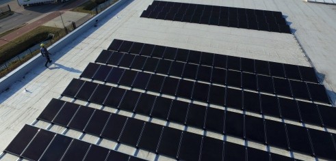
The true definition differs per region/standard, but in general a HLL consist of a flexible anchor line (cable, wire rope, fibre rope or webbing), attached to two or more anchor points. This type of fall protection system can be installed on top of structures such as roofs, but also in a wall or overhead situation. Users of the system shall connect themselves to the system by using a full-body harness and a lanyard.
Determining HLL compliance
Setting up a HLL system that is safe to use, isn’t as simple as installing some posts on a roof and connecting them with a cable. Each standard provides a range of requirements to which such a system should comply. Which requirements should be met, depends on the purpose of the system among others. Will it be used for fall restraint or as a fall arrest? Then, there are a wide range of variables which influence the behavior of the system, and thus determine if the requirements are met. Let’s have look at a few of them.
The 3 main criteria
When designing a fall protection system, there are three basic criteria which will have to be taken into account:
- The components and materials should be adequate in strength. They should be able to withstand the Maximum Arrest Load (MAL) and Maximum Arrest Force (MAF) they are exposed to in the event of a fall.
- The Maximum Arrest Force, addressing the forces allowed on the user’s body, has to be within the acceptable limit, so that the probability of injuries can be brought down to a minimum.
- Clearance: the distance from the working level to the lower level. If this is equal to or not greater than the required clearance for a fall arrest system to activate, only a fall restraint will suffice.
The next step
Above are the 3 main, basic criteria when designing a system. From here, more variables, maths and physics play a role in the performance of a HLL. The installer or supplier of the horizontal lifeline system, has to take into account the following variables when calculating a lifeline system:
- The surface on which the HLL is mounted.
- The distance between the anchor posts.
- The height of the anchor posts.
- The tension of the anchor line.
- The type of anchor line: cable (wire rope), fibre rope or webbing.
- The distance to the roof edge.
- The number of simultaneous users.
- The length of the lifeline system.
- The energy absorption mechanism.
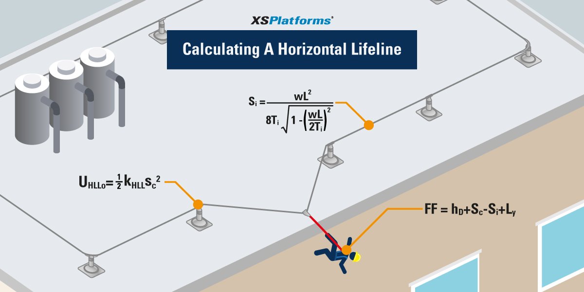
Calculating horizontal lifeline performance.
All of the above mentioned variables do not only affect the performance of the horizontal lifeline system, they also affect one another. They height of an anchor post for instance, will influence the loads that are applied on the extremity anchors in the event of a fall. As will the selected energy absorption mechanism.
You can imagine then, that calculating such a system is very complex. And as buildings and structures vary, each system has to be calculated individually. You can image that performing these calculations manually, increases the risk of miscalculations. For this reason, we strongly recommend the use of a lifeline calculation program.
Lifeline Calculation tool
A lifeline calculation tool such as ODIN will help prevent such miscalculations. Here, the user fills in a number of variables that vary for each project that include, but are not limited to, the following:
- Standard to which the system should comply:
- EN795:2012 & CEN/TS16415 (Europe)
- ANSI Z359.6:2009 (United States)
- CSA Z259.16-04:2009 (Canada)
- Purpose of the system: fall arrest or fall restraint.
- Location of the system: roof, wall or overhead situation.
- Installation surface: i.e. metal, concrete or wood.
- The number of users: 1-6 (if applicable).
Once all the variables are put it, ODIN uses a large database of test results and standardized mathematics to calculate if the requested system complies to the given standard. The results are put in an extensive report which tells the user if the system passes or fails the following 4 checks:
- Max. arrest force (MAF).
- Max. load on intermediate (MIL).
- Max. arrest load (MAL).
- Max. cable force.
Not only does such a program minimize the risk of miscalculation, it also reduces the time it takes to calculate the performance of a horizontal lifeline system. As an added advantage, it provides the end-user with a complete safety document which can be used in insurance or liability cases.
Download the leaflets – know the advantages
Would you like to know more about ODIN, the online lifeline calculation tool? Please visit the ODIN webpage, or download the leaflet for end-users that contains all the ODIN advantages as a user. If you want to become an XSPlatforms reseller and know what ODIN can do for your business, for example quicker quoting, download the leaflet for resellers.


4 Comments. Leave new
Clear and professional explanation
thanks
Hi, Great article.
Except the standards indicated for US & Canada are mis-printed. They should be:
– ANSI Z359.6:2009 (United States)
– CSA Z259.16-04:2009 (Canada)
Regards,
Doug
Hi Doug,
Thanks for your kind words and thank you very much for your comment. I have changed it immediately in the article!
Tienen una lista de proveedores en México?, Saludos