In an earlier blog, we described the importance of using a personal energy absorber (PEA) in a fall protection system. We did this by explaining the maximum arrest force (MAF) and maximum anchor load (MAL).
Now, we want to highlight another important factor that is needed to determine the forces that are released on a user’s body when a fall is arrested. This is referred to as the fall factor.
What is the fall factor?
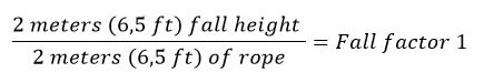
The fall factor is the ratio between the height of the fall and the length of rope that is available to absorb that fall. The value of the fall factor varies between 0 and 2 and is calculated by dividing the height of the fall by the length of the rope. The height of a fall is measured from the point where a person falls to the point that the fall is stopped.
The lower the value of the fall factor, the less impact forces are applied to the body of the person and the ‘safer’ the fall. On the other hand, the higher the value, the greater the impact forces on the body will be and the more likely it is that serious injuries are sustained. Note that the fall factor is a way to indicate the severity of a fall, not an exact way to measure impact forces.
Examples
To get a better picture of what fall factor is and how it’s calculated, we will provide some basic examples below, based on climbing images. As mentioned in the paragraph above, the fall factor is calculated following the equation:
![]()
Note that factors like elasticity of the rope and hitting objects are taken out of the equation.
Example 1
The anchor point of the climber is placed overhead and the rope is pulled tight during the climb. In the example, the rope length is 2 meters (6,5 ft). When the climber loses grip and falls, the fall distance is 0 because of the taut rope. This results in the following equation:
![]()
In this case, the impact force on the user’s body is minimal, which is a safe value for the climber. The person would sustain some bruises in most cases.
Example 2
In this example, the total rope length is 2 meters (6,5 ft) as well. But now, the person climbs higher up to the same height as the anchor point. If the climber should fall, the distance of that fall will be 2 meters (6,5 ft):
![]()
A fall factor of 1 is reached here, which means that impact forces come into play that can possibly injure the climber, like breakage of limbs or a concussion.
Example 3
The highest amount of force that is released on the climbers body is reached when the climber climbs to 2 meters (6,5 ft) above the anchor point with a rope of 2 meters (6,5 ft).
In case of a fall, the climber will fall a total of 4 meters (13 ft), resulting in the maximum fall factor:
![]()
The impact forces on the body are dangerously high when a fall factor of 2 is reached and the climber will sustain serious and possible life threatening injuries because of it.
In the table below, you find a schematic overview of the fall factors as described above:

Fall factor and fall protection systems
In practice, the examples given in the previous section aren’t representative for occupational situations where work at height is performed and fall protection is needed. In this section, we will put the examples into practice.
Fall factor 0
Example with an overhead fall protection system
When workers need to work at height and a ceiling or another structural element is located above them, the use of an overhead fall protection system is recommended. Especially in combination with an automatic fall arrest device (also known as a retractable device). This retractable device acts like a seatbelt: it keeps the lanyard taut at all times and will block immediately when a sudden acceleration occurs (a fall).
The image on the right shows that the fall distance is very minimal. Only the extension of the energy absorber will add to the fall height (in case a retractable device has a built-in energy absorber, the rope will not elongate). The lanyard will be the length of the distance between the attachment point on the harness and the anchor point, which is a horizontal lifeline in most cases.
If we do a basic calculation with the anchor point 1 meter (3,2 ft) above the attachment point of the harness, the fall factor would be:
![]()
Fall factor 1
Example with a wall-mounted lifeline system
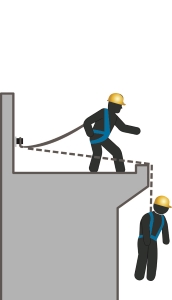 If the anchor point is located at waist height and the attachment point of the lanyard is located at the back of the worker, the fall factor will be around 1. In the example on the left, an overhead system is not possible, so the anchor point (a horizontal lifeline) is mounted at waist height on a wall.
In this situation, the lanyard is 2 meters (6,5 ft). When a fall occurs, the user will fall approximately 2 meters (6,5 ft) as well. The protruding working area will somewhat decrease the fall distance, but the deflection of the lifeline will add to that again..
The impact forces will be quite high in this situation, that’s why a personal energy absorber (PEA) needs to be used, which decreases the forces and decreases the chance of (serious) injuries caused due to those forces.
Fall factor 2
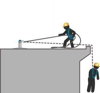 Example with a horizontal lifeline system
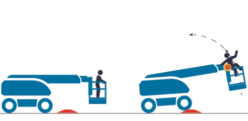
Horizontal lifeline systems and other systems where the anchor points are located at foott level are generally installed on roofs. When a user falls, they fall the distance of the attachment point to the height of the anchor point (2 meters / 6,5 ft) and the distance of the lanyard below the anchor point (2 meters / 6,5 ft).
In the example on the right, this means a fall distance of approximately 4 meters. When putting this into the equation, we get a fall factor of 2:
![]()
The impact forces that are released on the body will be very high. That’s why a personal energy absorber has to be used in these systems. This will add to the fall height by 0,75 meter (2,5 ft), but it will significantly reduce the impact forces and decrease the risk of serious injuries.
The most appropriate fall protection configuration
The examples given do not entirely cover real life situations, because elements like rope flexibility, use of an energy absorber, deflection of the wire rope, distance of the anchor point to the roof edge etc. will have impact on the impact forces as well. Also, the distance to the next level below the working area is not determined (fall clearance).
Nevertheless, keeping the above in mind will help in choosing the most appropriate configuration for your fall protection system: whenever possible, strive to minimize the fall factor to 0.
ODIN calculation tool
To help users, as well as installers of fall protection systems, XSPlatforms has developed a tool to determine if a lifeline system complies to local standards and is safe to use, taking all factors into account, including the impact forces.
Download the leaflet with all information and added value of ODIN below.

Also read our blog about calculating the fall clearance of a fall protection solution »


1 Comment. Leave new
Like